Types of control valves and their features. Regulating valves Buy a regulating two-way and three-way valve from the LDM company Control and technical characteristics
Control valves are used to remove rare and gas-like fluids that are transported by pipelines. The control valve allows you to continuously or discretely regulate the flow of the working medium into the pipeline.
For systems in which it is especially important to precisely distribute the flow of the working medium, a vise adjustment is necessary.
This is especially important, for example, for heat management, because the volume of heat transfer that occurs near the pipes and radiators determines the climate in the premises. The throughput capacity of the pipeline decreases or increases accordingly with a change or increase in the cross-section of the opening in the middle of the valve.
The problem arises from the constant change in the flow capacity of the pipe, which collapses the flow or gas behind the control valve.
There are three main types of control valves:
- two-way pass-through - to serve only for the treatment of vitrified water or gas that flows through straight sections of the pipeline;
- two-way coil – regulates the pressure and changes its direction, adjusts in places where the pipeline turns;
- tripass - mixes two types of working medium into a gas flow or divides one flow into two.

The simplest control valve is a straight-through valve, which is made up of the following parts:
- the body is in front of the tee, with a passage opening in the middle;
- flange or threads at the ends of the pipes;
- The valve is reinforced, which improves the tightness of the valve;
- shutter - the regulating organ of the valve;
- rod - a part that serves to change the position of the shutter.
The flow of the working medium is regulated by changing the size of the passage opening by moving the shutter position to the passage opening.
The design is frequently changed and supplemented with new elements depending on the purpose of the control valve.
Increase your respect! Find shut-off and control valves that have been modified so that the functioning of the working medium can be fully connected. In this case, the shutter is prepared in such a way that the parts in the closed position are hermetically sealed.
Advantages of control valves
This type of regulator is used in industrial and industrial water and gas supply systems, heat transfer systems and naphtha pipelines.
Regulating (shut-off-regulating) valves
The valves are designed for handling flows of rare and gas-like media that are transported by pipelines.
Regulating and shut-off-regulating valves operate continuously changing the regulated flow from the minimum when the valve is closed to the maximum when the valve is open.
Shut-off or valves control the flow not continuously, but discretely (the valve is open or closed). Both control valves and shut-off valves have small leakages of the regulated medium when the valve is in the closed position.
Please note that the division of valves into control valves, shut-off valves and shut-off and control valves is only in our region, as well as the standard for leakage for control and shut-off valves. The whole world vibrates simply control valves, the leakage of which is divided into six classes, the higher the class number - the less leakage. The remaining three classes are related to valves, which we call shut-off and shut-off-regulating.
Under the nominal diameter of the valve passage (D), consider the nominal internal diameter of the inlet and outlet pipes of the valve (for a number of outlets, the diameter of the outlet pipe may exceed the diameter of the inlet). The cutaneous value of the nominal diameter of the valve passage is indicated by the maximum possible value of the wasted adjustable valve, which, in turn, is due to low parameters (pressure differential, thickness, etc.). For ease of valve alignment and selection based on the results of hydraulic expansion of the required valve size, the concept of intelligent flow capacity has been introduced.
The valve capacity (Kvy) shows how much water at a temperature of 20 °C the valve can let through when the pressure drop is 0.1 MPa (1 kgf/cm2) with the valve closed.
The control valve consists of three main blocks: the body, the throttle assembly and the valve drive. Typical design of the walk-through
A shut-off and control valve without an installed actuator is represented by small number 1.
In the middle of the valve body 1, a throttle body is installed, which is folded into the seat 2 and the plunger 3, connected to the rod 4. The seat can be used in various structural configurations: screw into the valve body as shown in the valve body 1, press up to the body with a special bushing or bent jam.
The plunger moves in a straight line, aligning with the valve 5. A reinforced gasket 6 is installed between the body 1 and the valve 5. The rod 4 is guided out through the stuffing box 7, which is a set of spring chevrons ring with fluoroplastic-4 or its modification. A drive is installed on the valve 5, the rod of which is connected to the rod. The drive can be pneumatic, manual, electric or electromagnetic.
The throttle valve is a regulating and closing element of the valve. It is in this unit that the task of changing the flow passage of the valve is implemented and, as a result, changing its flow characteristics.
Specific combinations of sleeve-seat-plunger are selected based on the operation of the valve: differential vice, adjustable type
the middle temperature, the presence of tinkering, the amount of throughput, the viscosity of the middle, etc.
In most cases, the correct direction of supply of the working medium is important for the operation of the valve. It is marked with an arrow on the outer surface of the housing. If the middle is supplied through the left channel of the body, shown on small 1, this supply direction is called “to the shutter” (the middle goes to the plunger from below), and if the middle is supplied through the right channel, then this supply direction is called “to the shutter” "(middle) presses the plunger to the seat in a closed position). The main parameters and characteristics of typical control globe valves produced by industrial enterprises are presented in Tables 1 and 2.
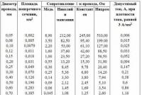
Table 1.

Basic parameters of shut-off control valves
Table 2.
The maximum capacity of shut-off and control valves

VIKONAVCHI MECHANISM
Drive and control mechanisms of shut-off and control, control and shut-off pipeline valves are recognized
For the rewinding of a kebogo signal (pneumatic, electric submarine) in the mechanical (linіine abstract) the rod of the rod of the grocery of the sorrostko by the corner of the puppet organ (valve, the culled shutter, disk of the salins, jerking the tocho).
The various mechanisms that are used to control shut-off and control valves based on the operating principle and type of energy to create the necessary mechanical force on the operating valve are divided into:
Pneumatic
Electric
Hydraulic
Combined
Pneumatic mechanical mechanisms
Pneumatic drive mechanisms, by tradition, occupy a great place among drives for various types of control valves. It is clear to us that mass industrial automation until the 50s and 60s of the last century was based largely on pneumatics. Pneumatic automated control systems today, in the era of microprocessors and widespread stagnation of digital electronics, look somewhat archaic, and in addition, they are cumbersome and require organization of preparation measures. This is due to the fact that the work of pneumatic systems is spent so much time in the compressed air.
At the same time, the simplicity of the design of pneumatic drives, and as a result of this, their high reliability and maintainability allow them to be successfully used in modern automated process control systems.
Pneumatic valve mechanisms are used to change the pressure of the return pressure P at the output of the regulator to move the regulating body - valve, flapper, gate, faucet, etc. The regulatory body changes the flow rate of radium, gas, steam, etc. at the control object, which then triggers a change in the regulated process parameter.
According to the type of drive, pneumatic and mechanical mechanisms are divided into membrane, piston, rotary, air motors, which are wrapped.
Membrane Vikonavchy Mechanism (MIM)
The diagram of the diaphragm valve mechanism (MIMu) is shown in figure 2. The movement of the output rod 2, connected to the control element, is influenced in one direction by the force generated by the vice P, and in the other direction by the force of spring 3. Signal P fit the sealed membrane head ", which contains a membrane made of gummed fabric with a thickness of 2-4 mm with a hard center. There is a spring 3 on the bottom of the membrane. In membrane-type mechanisms (Fig. 2), the pressure of the ceramic coating flows onto the membrane 4, pressed along the perimeter between the actuator covers, and creates a force that is activated by spring 3. In this way, the movement of the rod 2 drive proportional to the size of the fuel vice. The stiffness and front compression of the spring determine the range of force of the drive and the nominal stroke.
Membrane mechanisms are classified according to the size of the membrane “heads”. We are supplied promptly
with regulatory bodies - valves. Since, when the pressure P is removed, the membrane immediately moves up, then, in keeping with the design of the control body, the normally open ALE and normally closed NC valves are separated.

Malyunok 2. Membrane valve mechanism, installation on the control valve:
1 – regulatory body; 2 – rod; 3 – spring; 4 – membrane; 5 - oil seal
The static characteristics of most of the particles are close to linear, however, they form a hysteresis zone, which becomes 2-15% of the highest value of R. This value must be kept by vigorously rubbing in the gland 5, due to the difference of the vice on the line. vocal organ, depending on the characteristics of the spring and the effective flatness of the membrane.
To change the hysteresis zone and improve the dynamic characteristics of the MIMs, additional tension forces, called positioners, are installed on the final mechanism. There are different positioners who work behind the displacement compensation circuit and behind the force compensation circuit. In positioners of both types, the MIM has a negative coupling behind the rod positions, which turns off the flow of rubbing forces into the oil seal, the difference in the pressure on the control body, etc., to the static characteristics.
At the same time, there will be an increase in the amount of waste that goes into the MIM, and the dynamic characteristics of the rest will noticeably decrease.
To receive electrical signals from control systems, use electro-pneumatic positioners, which, in addition to enhancing the static characteristics of the membrane-conducting mechanisms, ensure the conversion of the electrical signal into a pulse of the ceramic air, which is applied Available on MIM.
The main technical characteristics of MIMs are presented in Table 3.
Table 3.

External appearance of typical MIMs that are installed on valves, that are adjusted, representations on the baby 3.

Piston pneumatic drives
Piston pneumatic actuators (PPD) are stuck in these situations when linear movement of the piston rod is required
- a variety of pipeline fittings, the main task of which is changing the vice on the pipe line. Replacing the working medium is carried out by changing the area directly through the passage opening in the valve body. Regulatory valves are divided into two types: two-way and three-way.
Two-way control valves. It lies directly in the flow of the working medium. The walk-throughs are installed on straight sections of the pipeline, at the end of the pipeline in those places where the pipeline requires turning.
Three-way control valves simultaneously with the regulatory function contribute to the desired mixing and flow of the working medium, as a rule, this type of control valve has three inlet-outlet pipes, according to their designation.
Device and principle of operation of a two-way globe valve
The main device is a body with a rotating opening in the middle; a fixation system on the pipeline and a regulation mechanism, such as a plunger or spool valve, are installed on the body. The shutter, after changing its position, before the passage opening, changes its area, thereby regulatingly obliging to pass through a new, working middle.
The fittings are divided according to the method of regulation. Depending on the type of shutter:
- Sedelnaya;
- Zolotnikova;
- membrane;
- cartatius.
The mechanism can be adjusted either manually through an injection on the rod or through an additional external control system.
The three-way control valve is placed underneath or mixed with the flow of the working medium. Vikorist is most often used in scorching systems.
The design of a device of this type consists of a metal body with three pipes. An internal partition with two open passage openings, one per skin outlet. The locking mechanism, fastened to the ceramic rod, can regulate the flow of the working medium through the skin opening, thereby regulating the pressure in one or two outlet pipes.
The control valve can be controlled either manually or automatically, depending on the system. This type of valve has a drive unit installed: a thermostatic drive, which changes the characteristics of the working medium, controls the temperature and pressure. In addition, other types of drives, such as electromagnetic ones, are used.
main advantages
Control valves are mainly installed on scorching systems. The body material is metal, which has high wear resistance and durability. These steels, chavuns and alloys of colored metals. This allows us to achieve high reliability of this type of fittings.
The main function of the control valve is to regulate the flow of the working medium, adjust the pressure and temperature in the system. Trikhodov, in addition, will also provide energy.
Technical characteristics
The main technical characteristics of control valves required for selecting and connecting them to the piping system are:
- Diameter of the mental passage;
- Type of hesitation;
- Type of fixation on the pipeline: flanged or threaded. Welded devices are becoming increasingly common;
- The range of changes in the working environment. The maximum and minimum temperature and pressure at which the control valve maintains its effectiveness;
- Material of the valve body and reinforced surfaces;
- Type of bath: manual, pneumatic, hydraulic, etc.
The installation of control valves is carried out mainly on systems that control the precise flow distribution of the working medium, most often in combustion systems. Control valves are also widely used in industry, when transporting rare and gas-like working media.
Shut-off and control valves are used to control the flow of fluid at industrial production facilities and wastewater systems. Main pipelines, oil and gas sources and factories from their processing, steel-smelting and chemical enterprises, purified water and water supply - the axis of only a small part of enterprises that require a large quantity of supplies regulating valves.
It is based on a variety of types and modifications of shut-off and control valves. We will look at the operating principle of the widest types of valves, such as valves, butterfly valves, gate valves, gate valves and diaphragm valves.
The principle for all overinsurance of most types of shut-off valves is approximately the same. All these devices either limit the flow of the medium (wind, liquid, steam, gas, dry bodies) or completely block it. The structural elements of shut-off valve types (membrane, disk, cage) are separated from each other and are prevented from blocking the flow.

The culvert valve is one of the most important elements of shut-off valves. Cranes of this type provide an even better ability to completely stop the flow once the shut-off element is turned a quarter turn (90°). Before the transfer of the rocker valve, it is also necessary to ensure a low closing hour, and a low flow rate, depending on the wear of the reinforcement
Culver valves can be divided into non-full flow and full flow. A non-full flow valve in an open position has a smaller passage diameter, which is lower than the diameter of the pipeline; a full flow valve has a smaller passage diameter that is similar to the diameter of the pipeline. The full-pass rocker valve is more effective because allows you to minimize the pressure on the valve.
The culvert taps are recommended for use either in the open or closed position. They are not designed to accurately regulate the flow or operate in a partially open position, which creates excessive pressure on the body, which can lead to deformation. Deformation of the body can lead to leakage and breakage.
The position is "open" |  |
|---|---|
Krok 1 |  |
Croc 2 |  |
The position is "closed" |  |
The butterfly valve regulates the flow of another special element - a disk mounted on the shaft, and around its axis, which rotates. Also, like the culvert valve, the butterfly valve can be closed in just a short hour, since the disc makes a 90° rotation, which is why this valve is also called a quarter-turn valve.
Depending on the position of the disc and shaft according to the body, the butterfly valves can be tri-eccentric or double-eccentric. The shutter with offset eccentricity means that the entire disk is displaced to the geometric axis of the body, which ensures a better fit of the disk to strengthen the shutter, and then prevents leakage.
Butterfly valves are characterized by simplicity of design, light weight and compact dimensions. Other materials that are cured during the manufacture of valves can prevent them from stagnating at very high temperatures or in aggressive environments. Basically, there is a need to strengthen the shutter, which is made from polymer materials.

The position is "open" |  |
|---|---|
Krok 1 |  |
Croc 2 |  |
"Closed" position |  |
The shut-off and control valve is suitable for use at various technological facilities, except large diameter pipelines, To control and regulate the flow of the media.
The operating principle of the valves does not differ much from the operating principle of other shut-off and control valves. The advantages of these valves lie in the small stroke of the shutter for complete ventilation; apparently, such a valve is small in size and has a pleasant weight. Also, the valve has a high tightness, and the reinforced valve does not rub against the seat, which significantly speeds up its wear.
Few parts of this type of valves rely on strong hydraulic support, and, obviously, high energy consumption, limiting the maximum diameter of pipelines on which they can be installed, as well as existing stagnant zones (through an S-like internal cut), where houses and smitty.
The position is "open" |  |
|---|---|
Krok 1 |  |
Croc 2 |  |
The position is "closed" |  |
The design of the gate valve resembles a gateway - the flow is regulated by a slide on the floor behind an additional metal plate - gate. The slide valve is one of the simplest devices for regulating flow.
The sliding gates, depending on the design of the locking element, can be wafer-type, double-sided or knife-type.
Before transferring the gate loading, it is necessary to ensure that this type of loading in an open-air plant does not contain liquid elements that interfere with the flow.

The position is "open" |  |
|---|---|
Krok 1 |  |
Croc 2 |  |
The position is "closed" |  |
Membrane valves are used as a shut-off element to seal the membrane (diaphragm) using the “pinch” method to tighten the flow of the valve, sealing the membrane.
One of the advantages of the diaphragm valve is that the components of the valve itself are reinforced in the flow of the medium, so that in some aggressive media the valve service life is longer due to regular maintenance and timely replacement of the membrane.
These types of valves, as a rule, are not suitable for aggressive media, and media with high temperatures, and generally cause stench for water supply systems.

Below is a video that clearly shows the principle of operation of a trieccentric disc valve
A control valve is a different type of pipeline fittings, designed for continuous or discrete change of pressure of the transported working medium to further change its flow passage.
This article examines the design features and operating principles of control valves. You learn about their varieties, marking and methods of installation on a non-supporting pipeline.
Zmіst statі
Classification and scope of valve sealing
The control valve is the largest type of fitting for changing the pressure of the medium circulating through the pipeline. Such structures are used in industrial and mineral water supply systems, gas supply systems and highways for transporting oil and gas.
Depending on the shape of the body, the valves are divided into the following types:
- pass-throughs - do not directly alter the flow of the working middle, they are mounted on straight sections of the pipeline;
- kutovi - change directly to the pipeline by 90 0;
- - The housing is equipped with three pipes (2 - inlet, 1 - supply), vikoristovuyutsya to mix two types of working medium in one flow.

The classification also depends on the method of fixing valves on the pipeline, which means that the fittings can be welded, flanged, coupling or fitting. In everyday use, the widest coupling structure is used, which is connected to pipes using an additional threaded connection; in industrial applications, it is flanged (connected with bolts and nuts through a special locking plate) and welded matura.
Features of the design and principle of operation
As an example, we will look at a flange-type control valve, the design of which is shown in the image.

The diagram shows the following assembly units:
- B – valve body;
- F – flanges, where the fittings are fixed to the pipeline;
- P - a cleft block that ensures the tightness of the valve and prevents the outlet of the medium being transported from between its body;
- S – rod that connects the valve drive to the shutter mechanism;
- T is a plunger that acts as a locking unit;
- V – throughput hole (seat), to which, when adjusting the vice, the locking plunger enters.
The operating principle of the valve is simple - the rod transmits the force that exits the actuator to the plunger, which descends and changes across the flow opening, as a result of which the pressure to pass through the valve or gas changes. This is to reduce the pressure in the pipeline and increase the fluidity of movement of the working medium. Since the plunger completely blocks the throughput opening, the pressure on the system becomes zero, ensuring complete sealing of the components that come into contact.
Features of variable control valves (video)
Varieties of control valves
Depending on the design of the control elements, the valves are divided into:
- saddle;
- klitinnu;
- membrane;
- Zolotnikov.
The seat valve, with its own design, can use 1 or 2 seats. Single-seat fittings have one flow opening, such structures are installed on pipelines of small diameters (up to 150 mm). The two-seat valve has an advantage in terms of a balanced plunger and can be used in systems with vice up to 6.5 MPa and diameter up to 300 mm. The locking plunger can be screwed into a plunger, a plate or a frequent one.

In valve-type fittings, the valve takes the form of an empty cylinder, which moves in the middle of the opening - the valve, which simultaneously acts as a direct connection and passage unit. The cylinder itself has a radial perforation, behind which it fits into the pipeline. The design features of the valve fittings ensure minimal noise and vibration during valve operation.
In addition to seat and valve valves, which can be equipped with a manual drive, the diaphragm fittings are supplied with or without hydraulic drives. Its seal is an elastic humic membrane (ordinarily a fluoroplastic membrane). The result can be brought to our attention and awakened.
Splinters of the flexible membrane can cause damage to the adjustable vice; the valve is equipped with an additional unit - a positioner, which controls the wide position that connects the membrane to the rod drive. The resistance of the humic seal to chemically aggressive media and corrosion is ensured by membrane structures, which allows such fittings to be installed on chemical industry pipelines and lines that transport naphtha products .

The spool valve regulates the pressure of the working center by turning the shutter (spool) to the right angle, which leads to partial opening or closing of the passage opening. The principle of operation of such fittings is similar to that most often found in the energy industry.
The advantage of spool valves is the need to apply minimal forces when operating the valve, since the pressure of the center in the throughput opening is practically not affected by the movement of the locking element. However, such designs are not able to ensure complete tightness of the working medium when the seat is closed, so they are practically not suitable for use on pipelines with a high vice.
Markuvannya
Technical requirements for control valves are outlined in the regulatory document GOST No. 12893 “Valves that regulate single-seat, double-seat and clump-type valves”. Conforms to GOST standards, all valves are of unified type marking 21h10nzh, in which:
- 21 – type of fittings (regulators and vices use numerical nomenclature 21 and 19);
- h - material of the body (h - chavun, s - carbon steel, b - brass or bronze, tn - titanium, p - plastic);
- 10 – drive type (for one – mechanical, 6 – pneumatic, 7 – hydraulic);
- NZ – material for the production of hardening surfaces, stainless steel.
The main manufacturer of valves is the Avangard company (Stary Oskol Valve Plant). Among foreign companies it is significant (Denmark) and FAR (Italy).